
Audersigt D2 PRO Stroke Adjustment: Seven Settings and Needle Protrusion
Audersigt Team·7 min read
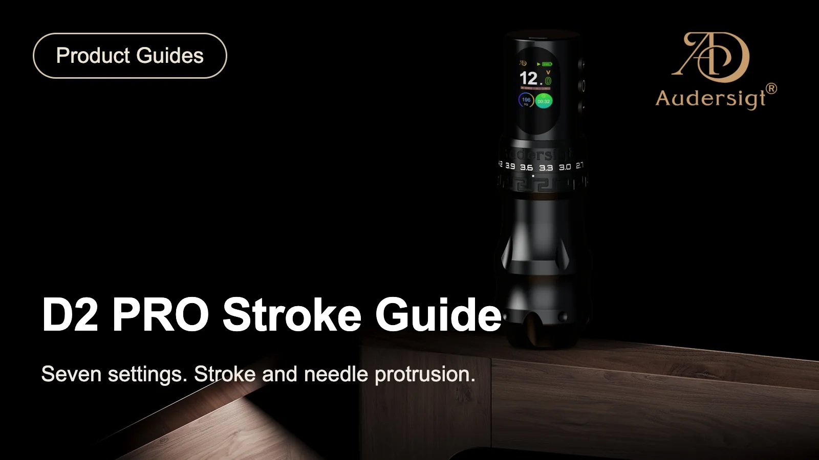
The Audersigt D2 PRO has two adjustments that are easy to confuse: the stroke selector changes the mechanism's travel, while the grip adjusts the cartridge position and needle protrusion. Selecting a 4.2 mm stroke does not set a 4.2 mm working depth.
This guide focuses on identifying those controls, recording the seven positions and checking the setup after a change. For the broader explanation of stroke, voltage and give, read the Tattoo Machine Stroke Guide. Here, the model-specific question is what to check on your D2 PRO—not which stroke every artist should use.
Identify the Two Controls Before Making an Adjustment
The D2 PRO product page documents seven stroke positions, separate stroke and needle-protrusion adjustments, and 32 mm and 41 mm grip options. Check the instructions supplied with your exact machine and selected package.
| Control | What it changes | What it does not establish |
|---|---|---|
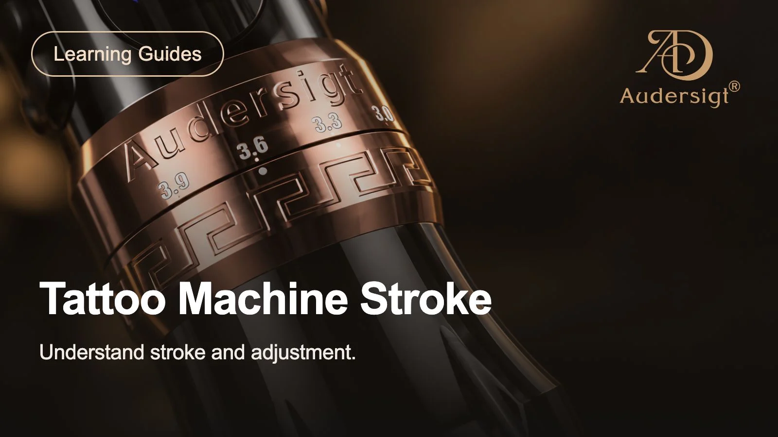
| Marked stroke-adjustment ring | Selected travel of the driving mechanism | Needle protrusion or penetration depth |
| Adjustable grip | Cartridge position relative to the drive, affecting needle protrusion | A different mechanical stroke setting |
| Voltage controls | The motor's operating behaviour | A change from one marked stroke to another |
Use the markings and supplied instructions to distinguish the controls. Do not identify an adjustment solely by the fact that a part rotates. Avoid forcing a ring, assuming a rotation direction or counting turns from an unverified starting position.
The Seven D2 PRO Stroke Positions
The documented sequence is 2.7 / 3.0 / 3.3 / 3.6 / 3.9 / 4.2 / 4.5 mm.
These are stroke specifications, not seven needle-depth presets or a technique prescription.
The useful feature is the ability to select and record different mechanical configurations on the same model. The longest position is not automatically the most suitable; nor does a short position guarantee a soft response. Cartridge resistance, motor operation and the complete setup still matter.
A Practical Adjustment and Recheck Sequence
Follow the current D2 PRO instructions where they specify a procedure. The checklist below helps keep the two adjustments separate; it does not replace supervised training or provide a setting for use on a person.
1. Record the existing setup
Note the machine, grip option, marked stroke position and cartridge model. Keep the selected mechanical position separate from any description of needle protrusion. A record such as “4.2 mm stroke selected” is more precise than “4.2 mm needle depth.”
2. Stop the motor and follow the isolation instructions
Make adjustments away from the working area, with the motor stopped and the equipment secured as required by its instructions. Stopping the motor is an adjustment precaution; it is not evidence that the needle has parked at full retraction.
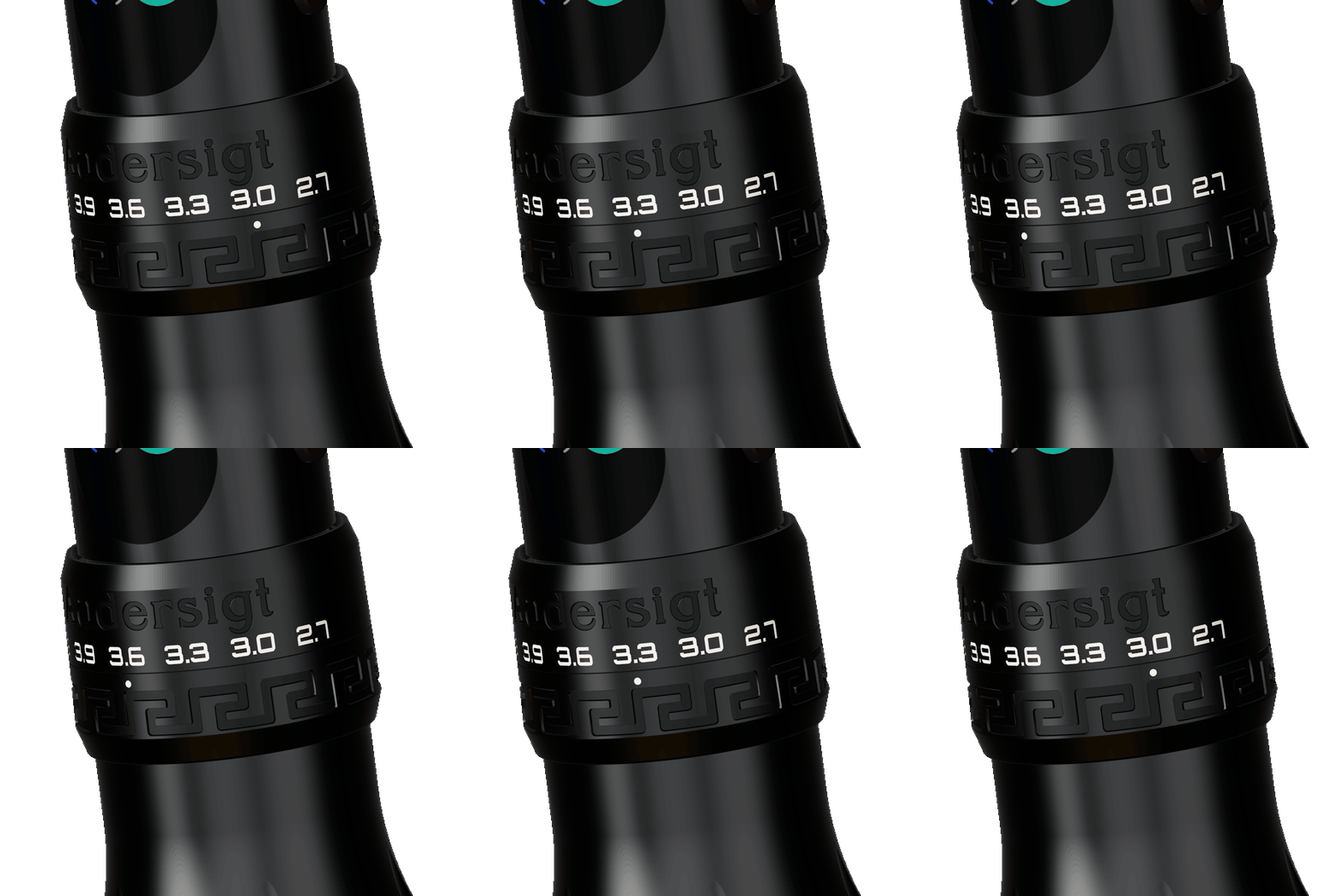
3. Use the dedicated stroke selector
Locate the marked stroke-adjustment ring and select the intended marked position according to the instructions. Confirm the selected marking. Do not force the mechanism beyond its range or assume a click, locking action or rotation direction that has not been documented for your machine.
4. Recheck the cartridge and grip separately
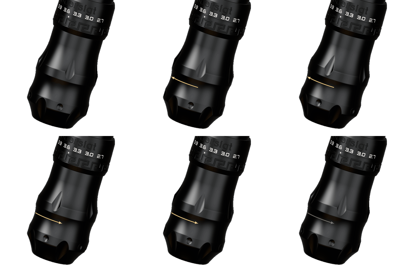
Confirm correct cartridge seating and inspect the setup as the instructions require. If the grip is adjusted, record that separately from the stroke selection. Changing the stroke can change the movement limits, so the previous grip position should not be assumed to give the same maximum protrusion.
5. Verify by an approved method
Do not place fingers, a ruler or another object against a moving needle. Do not open the machine or manually turn internal parts to reproduce a diagram. If you cannot establish the movement limits using the manufacturer's approved procedure or appropriate equipment, ask Audersigt support rather than treating a stopped snapshot as a measurement.
6. Document any supervised practice evaluation
On suitable practice material, record the cartridge and the setting being evaluated, changing one variable at a time within the instructions. Practice observations describe that setup; they do not validate a penetration depth, a safe technique for a person or a healed outcome.
Why the Stopped Needle Position Can Be Misleading
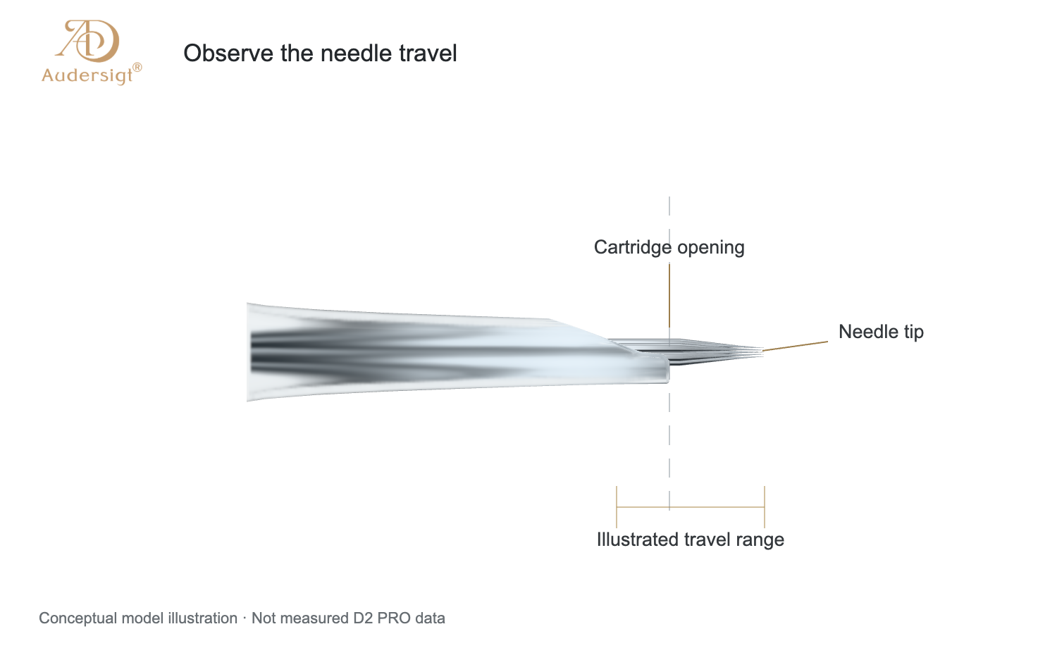
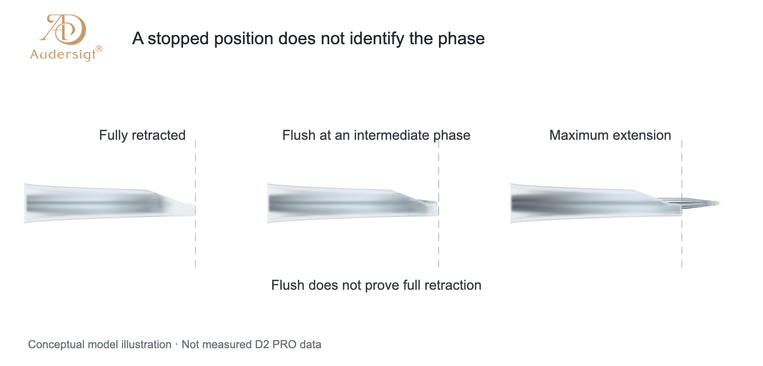
A stationary needle tip that appears flush with the cartridge opening tells you its position at that moment. It does not prove that this is the fully retracted end of its cycle.
Unless an exact model documents and verifies a defined parking position, do not infer one from pressing the stop button. The mechanism may have stopped between its travel limits. A flush-looking tip could therefore move both inward and outward when the cycle resumes.
For this reason, “flush when stopped” is not enough information to calculate maximum protrusion. It is also not a procedure for setting working depth.
Two 4.2 mm Examples: A Geometry Explanation
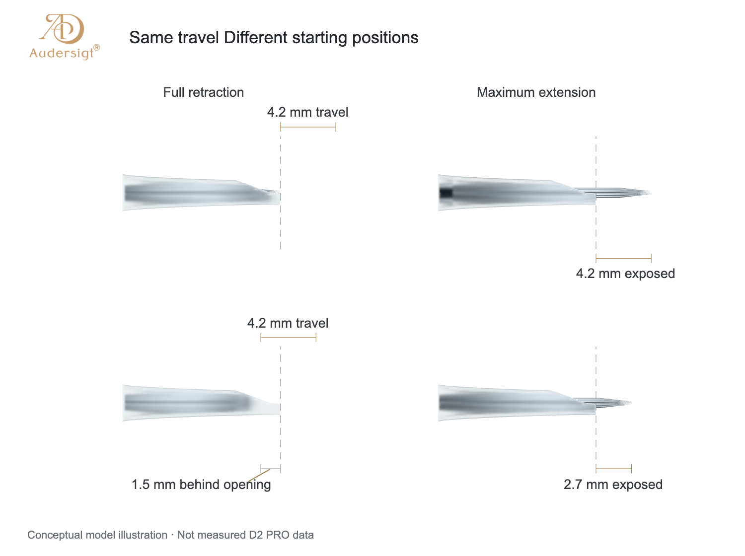
The following examples are idealised mechanical illustrations, not D2 PRO measurements or recommended needle exposure. They assume that actual needle travel equals the selected 4.2 mm mechanism stroke, that there is no lost motion and that the tip is not exposed at full retraction.
Take the cartridge opening as the reference plane. Let R be the distance the needle tip sits behind that plane at full retraction, and let S be the assumed actual travel. Under these assumptions:
Maximum exposed length = max(0, S − R).
| Idealised condition at full retraction | Assumed needle travel | Maximum exposed length in the model |
|---|---|---|
| Tip exactly flush: R = 0 mm | S = 4.2 mm | 4.2 mm |
| Tip 1.5 mm inside: R = 1.5 mm | S = 4.2 mm | 2.7 mm |
The first result equals the stroke only because the reference position is exactly flush at full retraction. The second uses the same travel with a different offset: 4.2 − 1.5 = 2.7 mm.
Neither example tells you how far a needle should enter skin. The numbers illustrate the difference between travel and position. They must not be copied as D2 PRO setup instructions or presented as measured cartridge behaviour.
A cartridge membrane, coupling and mechanical clearances can affect how a needle follows the drive. Establishing actual needle travel requires an appropriate measurement method; the nominal mechanism stroke alone does not prove it.
Changing Voltage Does Not Select Another Stroke Position
Changing the voltage setting does not move the stroke selector from 3.6 to 4.2 mm. It changes a different part of the operating configuration.
Likewise, changing the grip does not select another marked mechanical stroke. Keep all three entries—stroke, grip/protrusion adjustment and electrical setting—separate in the record. This makes later observations easier to interpret and reduces the risk of attributing a change to the wrong control.
For a broader equipment shortlist, see the wireless tattoo machine comparison. For needle grouping and size terminology, use the cartridge needle sizes guide.
Common D2 PRO Questions
Does a 4.2 mm stroke mean 4.2 mm of needle protrusion?
No. Protrusion depends on the cartridge reference position and actual needle movement. The value 4.2 mm describes the selected nominal mechanism travel.
Does a flush needle after stopping mean full retraction?
No. That observation alone does not identify the cycle position or maximum exposure.
Can the theoretical 4.2 mm travel produce 2.7 mm maximum exposure?
Yes, in the stated idealised model with 1.5 mm retraction. This is arithmetic under explicit assumptions, not a measured or recommended D2 PRO setting.
Is 3.6 mm the correct starting point for every beginner?
There is no universal position for every beginner or cartridge. Use the exact instructions and an appropriately supervised training plan rather than a preset from a blog.
What should be checked after changing stroke?
Confirm the selected marking, cartridge seating and protrusion-check procedure. Do not assume the previous grip adjustment gives the same movement limits.
Explore the D2 PRO Configuration
The seven marked positions provide a way to compare configurations without confusing stroke with protrusion. Identify the correct control, record the position, recheck the cartridge and keep geometric examples separate from measurements and working-depth decisions.
View the Audersigt D2 PRO and its current package options, or contact support for instructions matching your exact machine.
Product information checked on November 9, 2026. The calculations illustrate a simplified model and do not establish skin penetration depth, cartridge compatibility or measured D2 PRO travel.
For battery capacity, runtime estimates and fair testing, see the D2 PRO vs B6 battery-life comparison. Check current configurations on the D2 PRO and B6 product pages.
Find your next tattoo setup
Shop productsRelated Articles
Best Tattoo Stencil Printers: X6 vs T08FD
Compare the Audersigt X6 and T08FD tattoo stencil printers by paper support, connectivity, battery, controls, size, and real studio workflow.
Best Wireless Tattoo Machines: A Specification-Led Studio Guide
Compare Audersigt D2 Pro, KT088, KT108 and MAX PRO by documented stroke, battery and grip configurations, with a practical buying checklist.
Tattoo Machine Stroke Guide
Understand stroke, needle protrusion and depth, then compare machine settings, cartridges and power systems without relying on a universal setup chart.